| Home |
| Misc |
| Linux |
| TCP/IP |
| Windows |
| Random Daodejing |
| Photos |
TCP/IP Notes
Intro / Network Addressing / Network Addressing IPv6 / Packet Headers / Networking and Data Link Layers / Transport Layer Protocols / Application Layer Protocols / IP Routing / ICMP / DHCP / Name Resolution and DNS / Security
NETWORKING AND DATA LINK LAYERS
TCP/IP protocols are the programming code which have become standardized and implemented within various operating systems and firmware for internet devices (e.g. routers). Packets are made up of bits and bytes; in fact by looking at the packet structure one can see how single bits, either in a "0" or "1" state can make the difference in how a packet functions.
The intersection between physical media (copper wires, fiber optic, wireless) and upper-layer protocols comes in the form of MAC (media access control). Each MAC device has a unique ID number (24 bit manufacturer ID & 24 bit serial number). Any point at which a sender passes a message beyond a local subnet becomes a default gateway (for example a router). In this case the router may then forward the transmission to another router (and from there another, ..) in a series of hops which designate the route in which packets are sent ("packet forwarding").
The Data Link Layer serves two primary functions:
- Media Access Control (MAC)
- Creating temporary point-to-point links between MAC addresses (Logical Link Control or LLC)
In the 802 family of networking specifications, the Data Link Layer is subdivided along these two functions. In order to enclose data packets (data encapsulation), protocols such as PPP (Point-to-Point) and ATM (Asynchronous Transfer Mode) are used. Special handling is necessary for X.25, frame relay, and ATM WAN Links (e.g. packet switching), otherwise point-to-point links do not require specific Data Link Layer addresses.
Data encapsulation at the Data Link Layer involves:
- Addressing (for WAN links)
- Bit-level integrity check - checksums calculated before and after transmission.
- Delimitation - provide markers on Data Link frames, header and trailer distinct from payload.
- Protocol Identification (PID) - service used to identify protocols used by packets, PID in header.
Point-to-Point Protocol (PPP)
-------------------------------------

PPP is detailed in RFC 1661 (https://tools.ietf.org/html/rfc1661) to provide encapsulation methods capable of supporting simultaneous protocols across the same link, the Link Control Protocol (LCP) which negotiates point-to-point links (handles address and control field information during PPP link setup), and Network Control Protocols (NCP), which are Network Layer negotiation protocols.
PPP header and trailer fields include:
- Flag - 1 byte delimiter set to 0x7E, which indicates the end of one frame and the beginning of another.
- Protocol identifier - 2 byte field identifying upper-layer protocols used.
- Frame Check Sequence (FCS) - 2 byte field used for integrity checks as data is sent.
Default maximum MTU for PPP is 1,500 bytes, however LCP can specify higher or lower values between PPP peers depending on networking infrastructure.
Protocol units are referred to as 'frames' in the Data Link Layer. The Ethernet II frame type is standard for IP datagram transmission over ethernet. The PID for this is 0x0800 (0x86dd in IPv6). When an IP datagram is transmitted, the leading frame is put onto the datagram and checks to make sure that minimum and maximum size requirements are met (64 bytes - 1,518 bytes). The network interface controller then performs a CRD check (cyclical redundancy check) and places a value in the trailer (Frame Check Sequence field).
The two Ethernet frame types that TCP/IP can use are:
1) Ethernet II
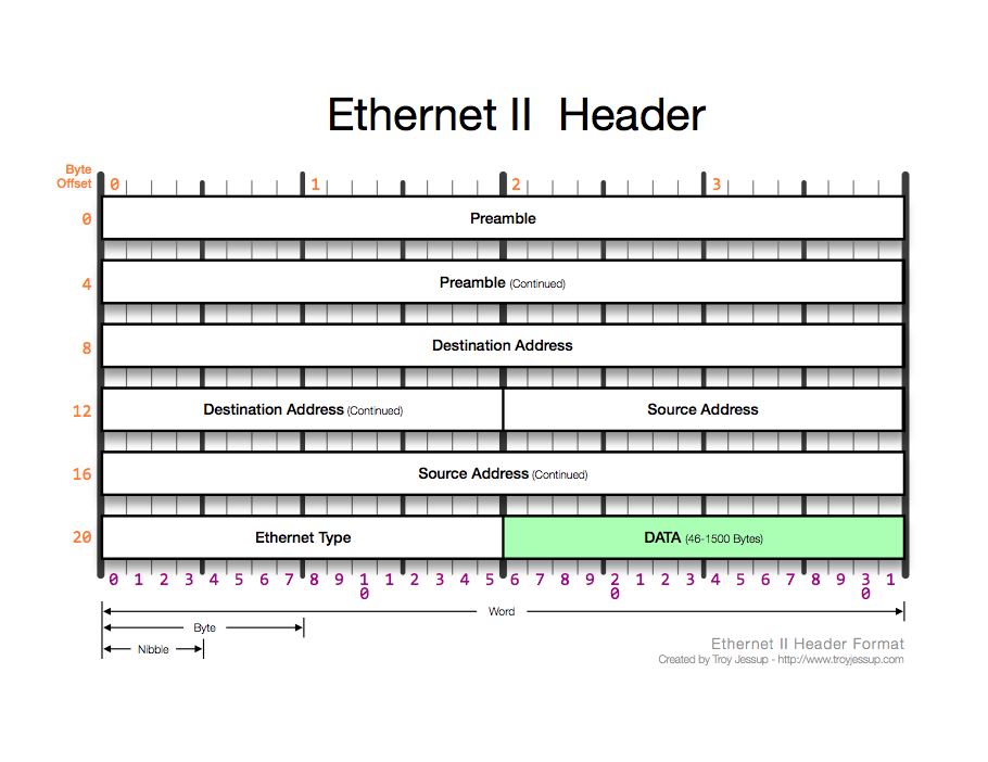
Preamble - 8 bytes. Precedes actual ethernet frame (not counted as part of overall frame length). Used by the receiver to interpret timing.
Destination Address Field - 6 bytes. Indicates MAC address of destination IP host obtained by ARP (broadcast, multicast or unicast).
Source Address Field - 6 bytes. Indicates sender MAC (can only be unicast).
Type Field - 2 bytes. Identifies protocols (assigned by IANA).
Data Field - 46 bytes - 1,500 bytes.
Frame Check Sequence Field - 4 bytes. Results from CRC calculation. Receiving IP host performs it's own CRC check and compares the results. The receiving NIC after verification strips the field and sends the frame to the Data Link Layer. From there, the frame is read to determine address and sent to IP.
2) Ethernet 802.2 Logical Link Control
Typically IP isn't seen as much over this frame type.
Preamble - 7 bytes. Does not end in consecutive 1's as in Ethernet II.
Start Frame Delimiter Field (SFD) - 1 byte. Indicates start of destination address field, both this and preamble are equivalent to Ethernet II preamble.
Length Field - 2 bytes. Indicates byte count in data portion of the frame.
Destination Service Access Point Field (DSAP) - 1 byte. Indicates destination protocol (defined by IEEE).
Source Service Access Point Field (SSAP) - 1 byte, indicates source protocol.
Control Field - 1 byte, indicates whether frame is unnumbered format (connectionless) or informational/supervisory format.
& like Ethernet II:
Destination Address
Source Address
Data
Frame Check Sequence
Address Resolution Protocol (ARP)
---------------------------------------------
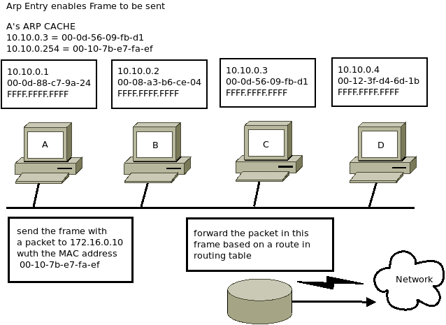
Used by IPv4 to resolve Network Layer (IP addresses) into Data Link Layer. ARP ( https://tools.ietf.org/html/rfc826) requests are sent by IPv4 nodes to receive hardware addresses. Unlike IPv4, IPv6 does not use ARP. Instead, it uses Neighbor Discovery Protocol (NDP). NDP runs over ICMPv6 and uses multicast rather than broadcast packets.
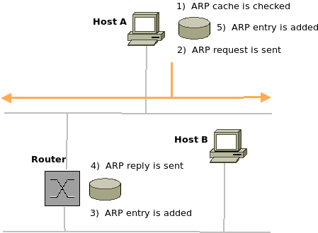
IP hosts maintain an ARP cache which is a table of hardware addresses, referenced first before sending an ARP request. ARP only finds local IP hosts; if the destination is remote, the IP host refers to the routing table (route resolution process). In a sense, ARP is almost like a "local" (Data Link Layer) version of the Network Layer routing process.
The ARP frame structure:
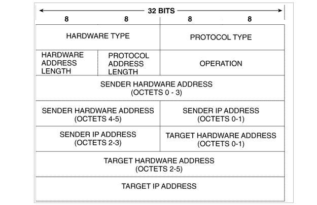
Hardware Type Field - determines hardware/data link type and hardware address length (https://www.iana.org/assignments/arp-parameters).
Protocol Type Field - determines protocol address type, uses same protocol ID numbers as in Ethernet II.
Length of Hardware Address Field - defines the length of hardware address (redundant).
Length of Protocol Address Field - defines length of protocol address (redundant).
Opcode Field - determines whether ARP packet is a request or a reply.
Sender's Hardware Address Field - indicates hardware address of IP host sending request or reply.
Sender's Protocol Address Field - indicates protocol or network address of IP host which sends request or reply.
Target Hardware Address Field - indicates target host hardware address. In ARP requests, the field is all 0's, in replies, the field should contain hardware address of desired IP host, and the hardware address of the next router in the path to destination (next-hop router).
Target Protocol Address Field - indicates target host protocol or network address.
Oftentimes this is the procotol which detects problems with networking configuration. One example being the use of ARP to find duplicate IP addresses on a network (gratuitous ARP).
The ARP cache is kept in memory under most operating systems, as well as tools for adding from configuration files and deleting entries.
The command arp -a can be used to see table contents (https://www.unix.com/man-page/Linux/8/arp/).
Addresses can also be obtained via the ipconfig command in Windows, ifconfig in Linux.
Proxy ARP allows simplified subnetting design and enables a router to reply to an IP host ARP broadcast:
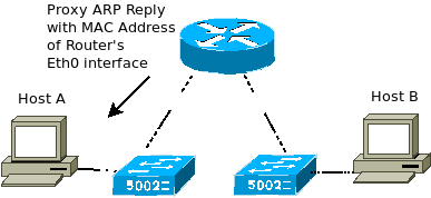
Reverse Arp (RARP) was used to obtain an IP address from the associated Data Link address but has been replaced by DHCP.
NDP Protocol
------------------
NDP (https://tools.ietf.org/html/rfc4861) replaces ARP in IPv6 in determining the presence of nodes, discovering link layer/IP layer addresses and finding routers. Similar to a request, NDP sends Neighbor Solicitation messages, formatted in ICMPv6:
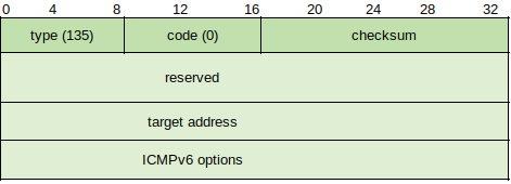
Most of the standard field rules apply, although future versions may supplant additional Options (currently the only option is the source node's link-layer address). Once the target host receives the solicitation method, it replies with a Neighbor Advertisement message.
IP Protocol
---------------
Network layer protocols are designed to send datagrams across networks via routers, defining source and destination Network layer addresses and determining how packets are sent.
The process for sending an IP message begins after the routing resolution process completes, or after it is determined whether a desired destination is local or remote. If a packet is intended for a remote destination, the IP host determines route entry based on the routing table. This can happen in two ways:
Host Route Entry - matches 4 bytes of destination address and indicates which local router can forward packets to the destination.
Network Route Entry - indicates that a route to the destination network is known but that a route to the individual host is unknown.
Typically, the router closest to the destination forwards the packets to the destination host. If neither host or network are listed, the IP host checks for a default gateway which provides a default route.
The receiving gateway typically does the following:
1) Forwards packet (provided there is a route).
2) Sends an ICMP redirect which points to another local router.
3) Sends an ICMP reply indicating that it's confused (destination unreachable).
When IP hosts cannot communicate, common reasons include:
- Destination is local but not replying to ARP because the destination is down or a duplicate IP address was detected.
- IP host can ARP only for local hosts but destination is remote.
- IP address source received from DNS is incorrect.
How IPv4 and IPv6 are different
------------------------------------------
Unlike IPv4, IPv6 packets cannot be fragmented by routers based on link MTU. Instead, a "Packet Too Big" ICMPv6 message is sent by the forwarding node at the point at which MTU limit is exceeded.
Whereas in IPv4 the source node determines if the route to the destination host is local or must be routed, IPv6 uses PMTU Discovery.
IPv6 uses multicast rather than broadcast. When IPv4 sends broadcast messages, all hosts within a local link must listen to the message to determine if it is meant for them. Conversely in IPv6 local link nodes will ignore this message.
In IPv6, NDP solicitation makes either static or dynamic configuration of the default router address unnecessary.
IP Datagram lifetime
---------------------------
IP packets have predefined lifetimes indicated by the Time to Live (TTL) field in IPv4 and the Hop Limit field in IPv6. The recommended starting TTL value is 64, and the default TTL value for Windows is 128. Although formally TTL is described as a number of seconds, in practice it is the number of hops (each time a packet is sent to a router, the router decrements the TTL field by 1).
Fragmentation and reassembly
-----------------------------------------
The reassembly process doesn't occur until all parts arrive at the destination. Before being sent to the Transport Layer, the fragments are recomposed into a complete TCP or UDP segment, or an error message will occur.
While IP handles fragmentation, the Transport Layer handles reassembly. Packets are given the same TTL values when fragmented, and if some take different paths to the destination may end up having different TTL values, however when the first fragment arrives at the destination the host begins counting down from the TTL from that fragment. Before this TTL expires all other fragments must reach the destination for the message to be considered complete. If incomplete, the destination sends an ICMP reply to the source indicating that the TTL has expired.
To fragment a packet, the router:
1) Places the original IP packet header ID field value into all fragments.
2) Decrements TTL value by 1 and places the new value in each fragment.
3) Calculates the location of the fragmented data (Fragment Offset field).
4) Sends each fragment off as separate packets with separate data link headers and checksum calculations.
On the receiving end, the host puts the fragments back in order based on the Fragment Offset value.
Service delivery options
--------------------------------
In the Preference field (packet priority-based) and Type of Service field (route priority-based) of IP headers, there is a way for a source TCP/IP stack to define treatment of packets, but this became supplanted by router-based QoS configuration. More recently both Differentiated Services (Diffserv) and Explicit Congestion Notification (ECN) have been proposed to address traffic priority issues.
Precedence can be characterized by several levels:
Level 0 - routine traffic
Levels 1-5 - prioritized traffic (real-time, e.g. VoIP)
Levels 6-7 - reserved for network/internetwork control packet
Type of Service (TOS) is used by routers to select a path when multiple paths are available.
IP routing
-------------
The routing table is a database which resides in the memory of the router, in which entries are known as "routes" and consist of a network address, a "next hop," metrics and vendor-specific information. Small networks may have only a few entries, whereas large enterprise networks can have hundreds. The routing tables of the Internet backbone routers contain over 100,000 entries.
The first job of a router is to determine where a packet's destination lay via Destination Address Field in the IP header. It then compares this with Network field values in the table. The methods used internally vary by manufacturer (not standardized).
A route entry can be placed into a table by three ways:
1) Direct connection - e.g. local subnets
2) Manual configuration - logging into the router via a web based interface and defining various options
3) Dynamically - configuration of router protocols (RIP, OSPF). For large networks this is not recommended for security reasons.
Routed protocols (different from routing protocols) are Layer-3 protocols used to send packets through an internetwork. Routing protocols can be used internally to achieve efficiency within a routing domain (IGP, used inside a routing domain and EGP to connect routing domains). Two different types are distance vector and link-state.
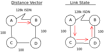
Distance Vector - periodically broadcasts entire routing tables to all neighbors in conjunction with timers to form a picture of network convergence (the time it takes for each router to have an accurate table). Also, this is characterized by distance.
1) Each router defines it's own distance vector as 0
2) Each router calculates distance to each connected link
3) Each router announces distance vector information
4) Each router updates it's routing table based on the announcements (triggered update)
5) Periodic broadcast or multicast of router information (periodic updates)
Link-State - each router generates information based on directly connected links, giving every router an identical network topology. The routers then use the Dijkstra algorithm (https://en.wikipedia.org/wiki/Dijkstra_algorithm) to determine optimal paths.
1) Hello process
2) Each router transmits link-state advertisements (LSA) containing lists of neighbors and the cost (based on link bandwidth) to reach them
3) Each router builds a picture of the network
4) A forwarding table is formed according to lowest-cost route
5) Link-state routers periodically broadcast database summaries on directly connected links
6) Routers can request updated information
Routing loops are a specific problem that can occur when a packet is routed through the same routers over and over again until TTL is 0. Various methods used to counteract this effect are:
Split Horizon - a router doesn't advertise a path in the same way in which it was discovered
Poison Reverse - focusing on route costs
Time to Live
Multicast vs. Broadcast update behavior - configure routers to forward multicasts
ICMP Router Advertisements - configure routers to send periodic ICMP Router Advertisement packets
Black Holes - occurs when ICMP is turned off and routers discard packets without sending a message
IPv6 routing
----------------
IPv6 was developed in part to address routing shortcomings in IPv4, including the way in which packets were designed. Many of the same protocols and approaches are similar to IPv4 with some differences, one of the most important upgrades the accommodation of 128-bit IPv6 addresses.
When an IPv6 packet is sent, the source node:
1) Specifies the value in the Hop Limit field
2) Checks destination cache
3) If a match is found between cache and destination address, the host receives the next-hop address, interface index and proceeds to check neighbor cache
4) The source host sets the next-address field value to the destination address, chooses the network interface and updates the destination cache
5) PMTU Discovery checks the routing path for the smallest link MTU size and sets packet size
6) Checks the neighbor cache (neighbor IPv6 addresses and host MAC address) to see if it contains an entry matching destination address
7) If not, send a router solicitation message to request link-layer address of next-hop router
The router:
1) Error checks to verify that header field
2) Decrements the value of the Hop Limit field by 1
3) Checks destination cache to see if an entry exists matching the header destination address, gets the address of the next-hop router/host and verifies MTU size
4) Updates destination cache, manages next-link MTU size
5) Checks neighbor cache for next-hop address and acquires link-layer address or uses address resolution, updates cache.
The Destination node:
1) Error checks
2) Checks the packet header's Next Header field
3) Checks destination port
In all cases the standard ICMP processes exit as in IPv4 for situations where something doesn't match correctly.
Further Reading
---------------------
Medium Access Control (MAC)
https://erg.abdn.ac.uk/users/gorry/eg3567/lan-pages/mac.html
Interface Encapsulation Overview
https://www.juniper.net/documentation/en_US/junos/topics/topic-map/security-interface-interface-encap-overview.html
Path MTU Discovery
https://en.wikipedia.org/wiki/Path_MTU_Discovery
Point-to-Point Protocol (PPP)
https://www.cisco.com/c/en/us/tech/wan/point-to-point-protocol-ppp/index.html
IEEE 802.3 Logical Link Control
https://erg.abdn.ac.uk/users/gorry/course/lan-pages/llc.html
Ethernet Version 2 Versus IEEE 802.3 Ethernet
https://www.ibm.com/support/pages/ethernet-version-2-versus-ieee-8023-ethernet
Address Resolution Protocol (ARP)
https://barrgroup.com/embedded-systems/how-to/arp-rarp
ARP: Address Resolution Protocol
http://users.softlab.ntua.gr/~sivann/books/tcp-ip-illustrated/arp_addr.htm
Address Resolution Protocol (ARP)
http://linux-ip.net/html/ether-arp.html
Address Resolution Protocol (ARP)
https://wiki.wireshark.org/AddressResolutionProtocol
The Internet Protocol (IP)
https://notes.shichao.io/tcpv1/ch5/
IPv6 Neighbor Discovery
https://www.juniper.net/documentation/en_US/junos/topics/topic-map/ipv6-neighbor-discovery.html
IP routing
https://en.wikipedia.org/wiki/IP_routing
IP Routing: Protocol-Independent Configuration Guide
https://www.cisco.com/c/en/us/td/docs/ios-xml/ios/iproute_pi/configuration/xe-3s/iri-xe-3s-book/iri-iprouting.html